Prusa-box compatible spool holder with load cell
Product information
Product name:
Prusa-box compatible spool holder with load cell
Product type:
3D models
Platform:
Prusa-box
Dependencies:
None
Download:
Latest version
Older downloads:
Download list
License:
CC BY-NC-SA 4.0
Statistics
Downloads:
11
Page views:
1112
Introduction
This design allows for mounting an HX711 and load sensor on top of the Prusa-box 3D printer enclosure. It replaces the top mount mod, and allows using the Filament Scale Enhanced plugin to measure the remaining amount of filament on the spool.
It's designed to use a minimal amount of soldering, and you can build it with no soldering at all if you can find an HX711 board that has the pin headers pre-soldered onto them. It uses an RJ45 8P8C connector to allow for modularity and ease of installation of the HX711 board in the box.
This guide assumes that you have already set up OctoPrint on a Raspberry Pi.
THE AUTHOR TAKES NO RESPONSIBILITY FOR ANY DAMAGES OR INJURY SUSTAINED TO YOU OR YOUR PRINTER, RASPBERRY PI OR OTHER HARDWARE. FOLLOW THESE INSTRUCTIONS AT YOUR OWN RISK AND RESPONSIBILITY.
The assembly guide is also available as a printable version here.
Materials I used
Tools
- Screwdriver with appropriate bits
- LSA/Krone punch down tool
- RJ45 crimping tool
- Wire cutter
- Wire stripper or a sharp knife
- Pliers (groove joint, but any will work) or Dupont cable crimping tool
- Small saw
- Soldering iron and solder (if you buy an HX711 board that does not have pre-attached header pins)
- Kitchen scale (or other reference scale for calibration)
Materials
IMPORTANT
The load cell that this design is made for, is:
- 75x12 mm
- Uses 4xM4 screws (not 2xM4 and 2xM5)
- Has a screw hole spacing for each pair of holes of 10.5 mm
- Wire length at least 20 cm
Many load cells are 80x12 mm, has other spacing, or uses different sized screws. You can buy them, but then you have to modify the SCAD file, because the provided STL will not work for you.
For the screws listed, you can also use longer screws within reason (e.g. you can use an M4x20 instead of M4x16, or M4x25 if you wish, but these are the recommended sizes and the ones I used).
- 1x RJ45 LSA keystone jack (e.g. this one)
- 1x RJ45 connector (e.g. these ones)
- 8x Dupont-terminated cables in various colors, 20 cm, female-to-female (e.g. this bundle of 40)
- 2x UY-3M Scotchlok connectors or Dupont connectors and crimping tool if you prefer crimping ends on cables yourself. I personally use these because they're very easy to work with, and can be used for many things.
- 1x Original Prusa filament spool holder (included with your printer)
- 1x HX711 board (either red or green should be fine)
- 1x 75x12 mm, 5 kg load cell
- 2x M3 nuts
- 2x M3x12 screws
- 2x M4 nuts (included with Prusa-box)
- 1x M4x10 screw (included with Prusa-box)
- 1x M4x16 screw
- 4x M4x20 screws
- 1x Zip tie
- PVC tape or other tape matching your enclosure. I've spray painted mine black, so I used black PVC tape.
- 2 meters of spare Ethernet cabling (or other similarly small gauge wires; you need two of the pairs, so four wires)
Printed parts
- 1x LCM-75x12mm-Base.stl
- 1x LCM-75x12mm-Holder.stl
- 1x HX711Mount.stl
I used 60% infill for the base and holder, and 100% for the parts that contact with the load cell directly. The HX711 mount doesn't need high infill. I personally used 30% because that's what the Prusa-box team recommends for most of their parts. Supports are not needed for any of the parts.
G-code for Prusa i3 MK3S+ with Prusament PETG is bundled with the download.
Installation
Filament holder
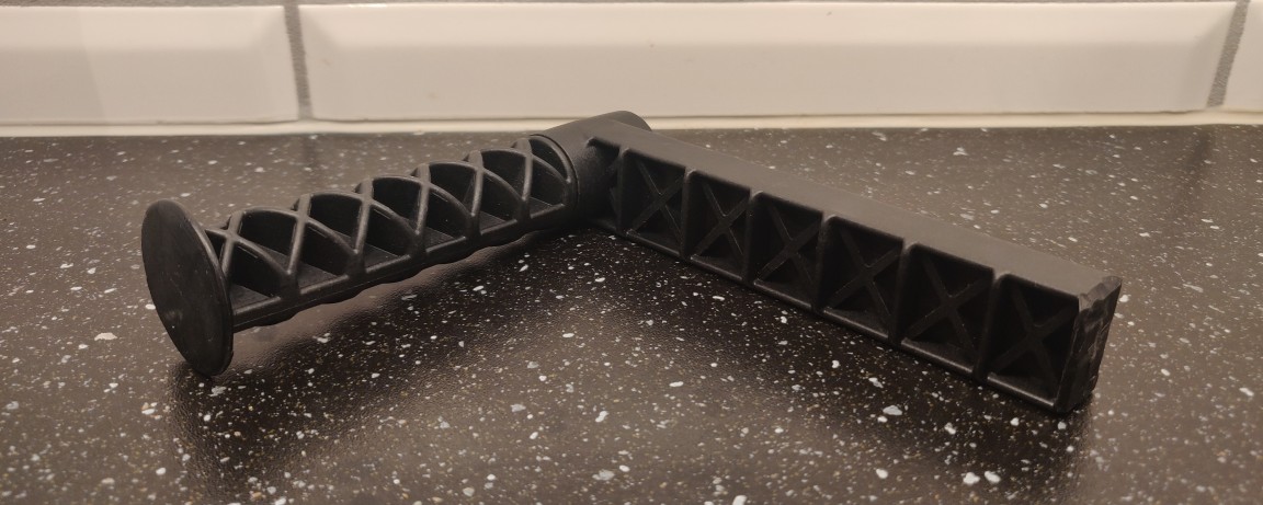
Saw off, melt away, or by any other appropriate method remove the clip part of the original Prusa filament spool holder. See below reference picture:
RJ45 keystone
I used Dupont wires in the following colors. You may use other colors, as long as you keep track of the colors used, because the ones below are used consistently throughout this document.
Colors used:
- Red, black, white, and green for load cell connections
- Orange, gray, blue, and brown for the Raspberry Pi-side connections
Cut all eight Dupont wires in half at the middle. You will use one half of each cable in this step. Keep the other halves of the brown and blue cables for later.
Using the LSA/Krone tool, terminate the following colors of Dupont wire, leaving as much spare wire as possible on the connector end of each wire.
| Wire color | Pin # | TIA-568-A | TIA-568-B |
|---|---|---|---|
| Red | 1 | Green/white | Orange/white |
| Black | 2 | Green | Orange |
| White | 3 | Orange/white | Green/white |
| Green | 4 | Blue | Blue |
| Orange | 5 | Blue/white | Blue/white |
| Gray | 6 | Orange | Green |
| Brown | 7 | Brown/white | Brown/white |
| Blue | 8 | Brown | Brown |
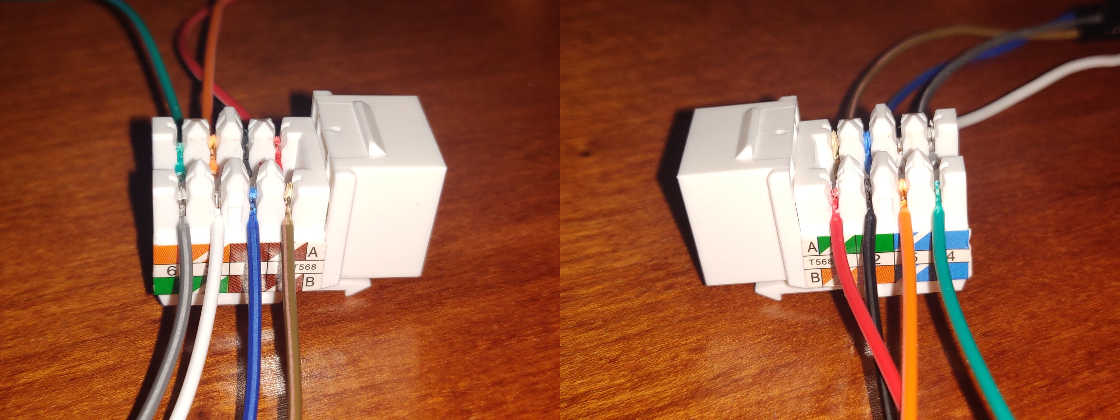
After terminating it, mount the keystone in the HX711Mount.stl printed file.
HX711 board
If the HX711 board you bought does not have the header pins soldered on yet, you should solder them on now, so you have somewhere to connect the Dupont wires to the HX711 board. Proceed when done.
Place the two M3 nuts in the clamp bridge (the small part from HX711Mount.stl). Screw in one screw from the underside of the mounting plate, through one of the nuts, with the nut facing up and away from the base plate. Slide the HX711 board in underneath the clamp, and insert the other screws. Very carefully tighten the screws so the HX711 board is held in place. Do not over-tighten the screws or you will break your HX711 board! Refer to the pictures below to see how the board is mounted.
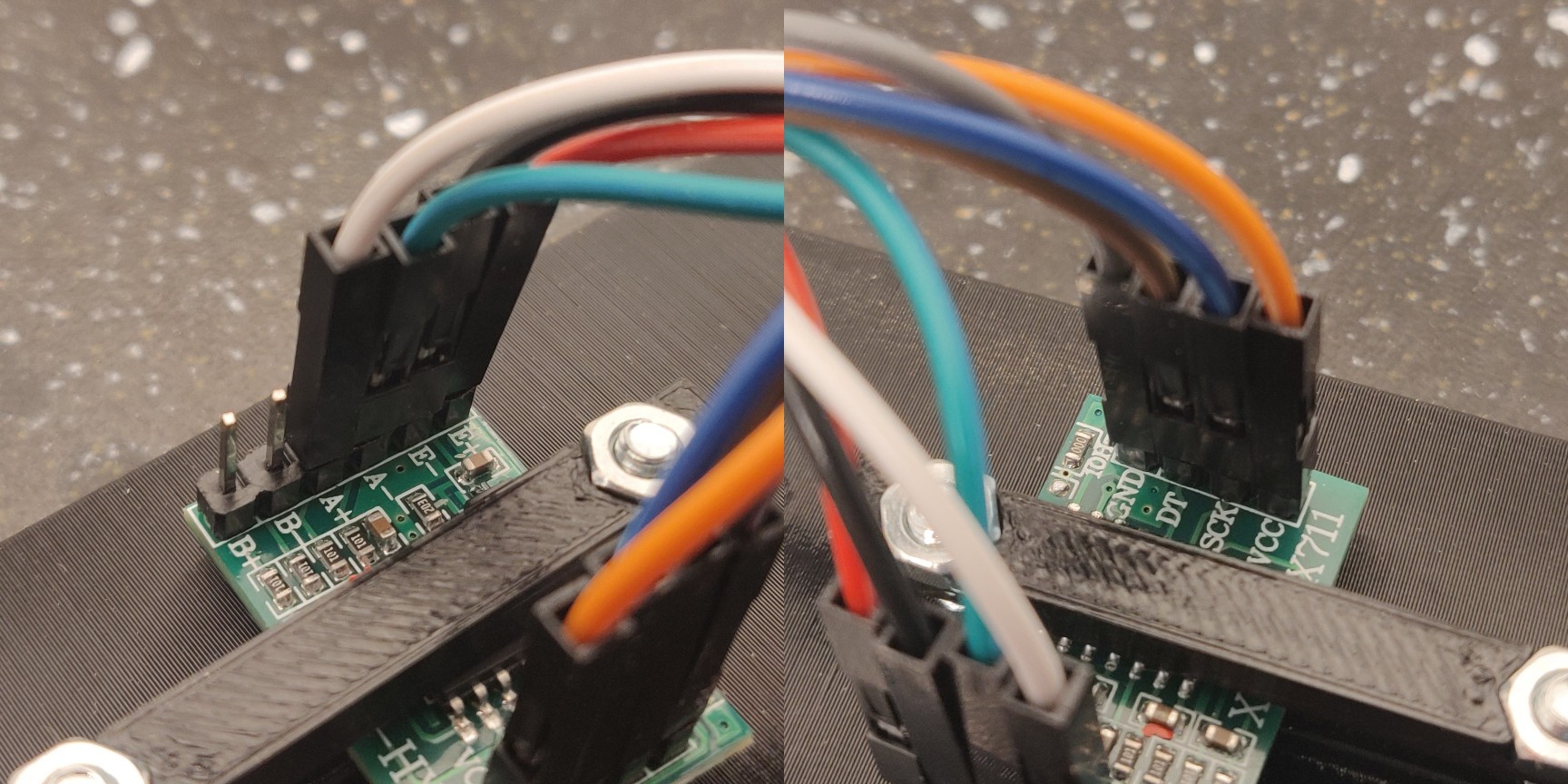
Connect the Dupont wires from the keystone jack to the HX711 board in this configuration:
- Red to E+
- Black to E-
- Green to A-
- White to A+
- Orange to VCC
- Blue to SCK
- Brown to DT
- Gray to GND
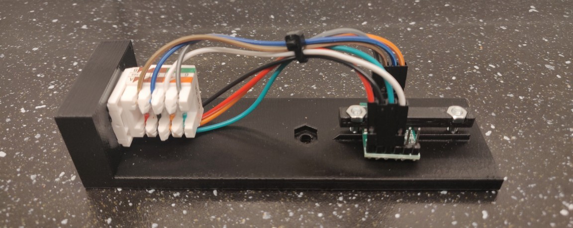
The final result should look like this:
Use a zip tie to bundle the cables neatly together. The finished plate should look like this:
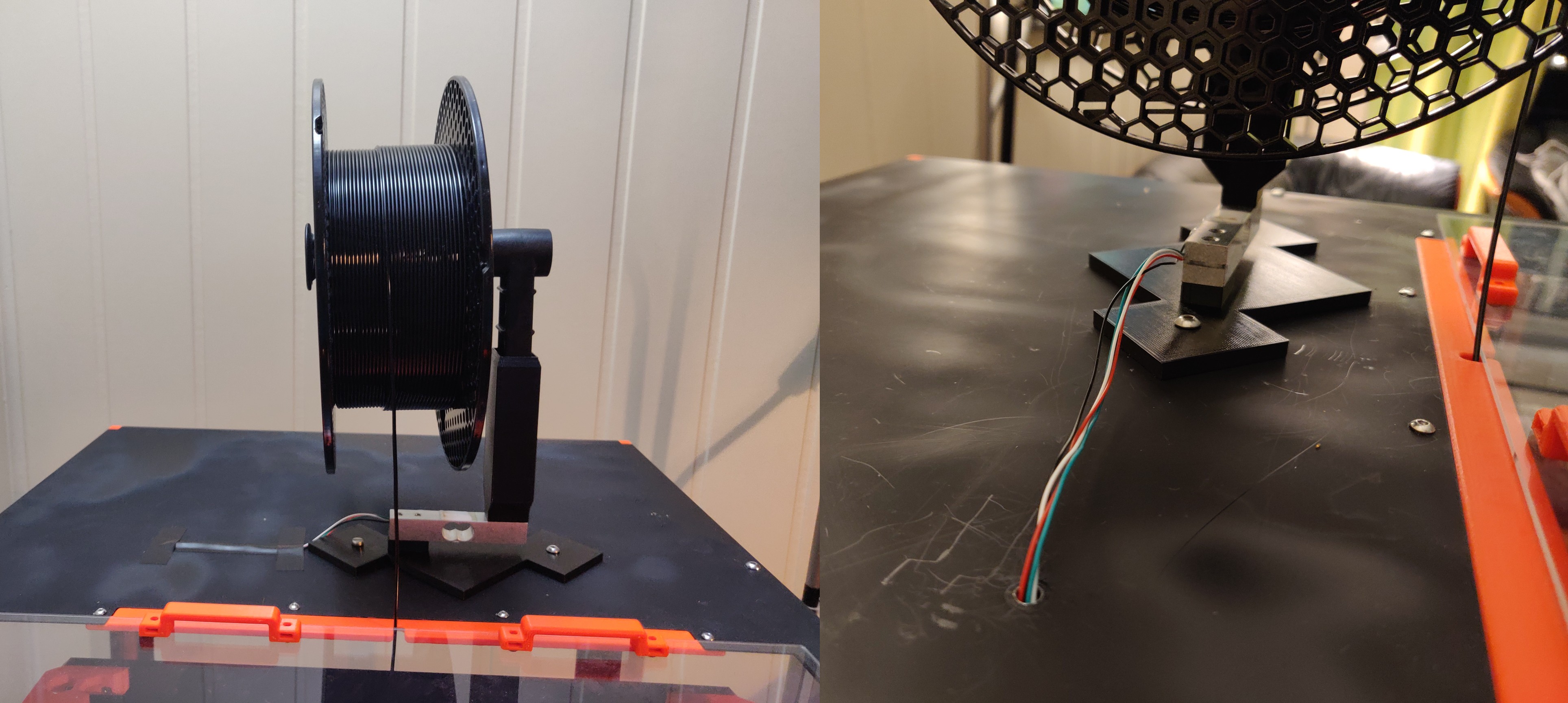
Spool holder
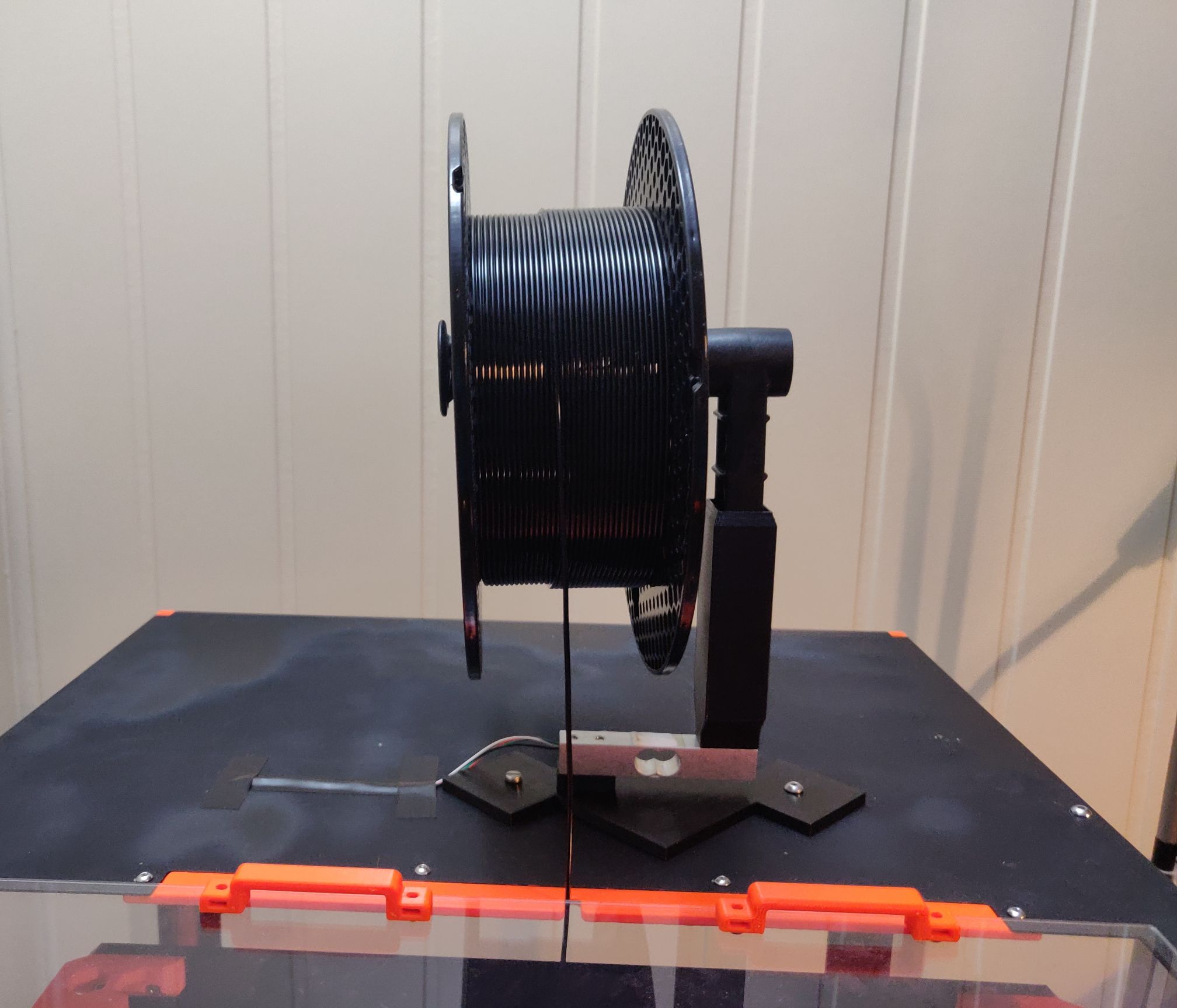
Mount the load cell to the spool holder part first (the tall, hollow piece). This is the piece that you will put the sawn-off Prusa spool holder in. Use two M4x20 screws for this. The spool holder has screw holes inside it, and you should put the screws in from inside this hollow printed part, screwing them from there down into the load cell. You'll probably need a fairly long screwdriver. Make sure that the load cell is correctly oriented; there should be a sticker or etching on the small vertical side of the load cell on the same side as the printed holder, pointing down and away from the printed holder.
After the spool holder is securely mounted, attach the load cell to the base plate using two M4x20 screws. These screws are inserted from the underside of the plate.
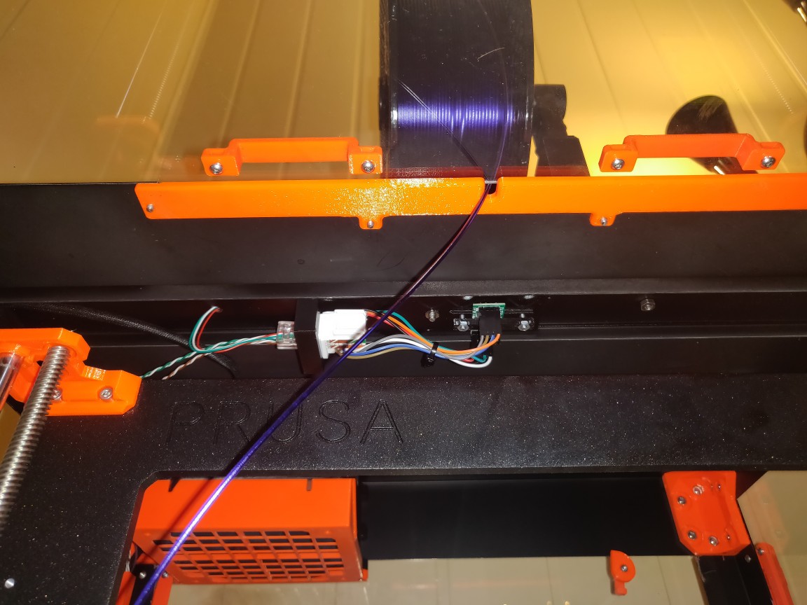
While facing the front of the printer enclosure, mount the base plate to the top of the box on the middle and adjacent right screw holes through the cross beam in the printer box. See picture below for illustration. Use an M4x16 screw for the middle (left) hole, and an M4x10 screw for the right one. These screws are inserted from the top of the plate, and are screwed down through the roof of the print enclosure.
The right/short screw should be secured with an M4 nut directly on the underside of the printer box roof. The left/long screw should be screwed through the HX711 mounting part, in between the cross beam in the roof of the enclosure. There is an M4 nut slot in the HX711 mounting plate - it does not retain the nut on its own, so you'll have to hold it in place while you put the screw through it from above.
Note: Make sure that when you mount the HX711 mounting plate in the cross beam on the underside of the enclosure roof, that the keystone faces left!
Lastly, guide the four wires from the HX711 cell through the cross beam hole to the left of the spool holder on the top of the enclosure. Cover these wires with some PVC tape.
RJ45 connector
Start by stripping the outer jacket of the Ethernet cable piece and extract two of the twisted pairs inside. Make sure not to damage the insulation of the twisted pairs themselves. I used the green and brown pairs.
If there is exposed wiring at the end of the load cell wires, cut these off so that there is no exposed wire. The insulation will be crimped through when you crimp the RJ45 connector.
Crimp the RJ45 connector with cables in this order, from left to right, with the clip facing down:
- Red wire from load cell
- Black wire from load cell
- White wire from load cell
- Green wire from load cell
- Green wire on twisted pair cable
- Green/white wire on twisted pair cable
- Brown wire on twisted pair cable
- Brown/white wire on twisted pair cable
See the following illustration:
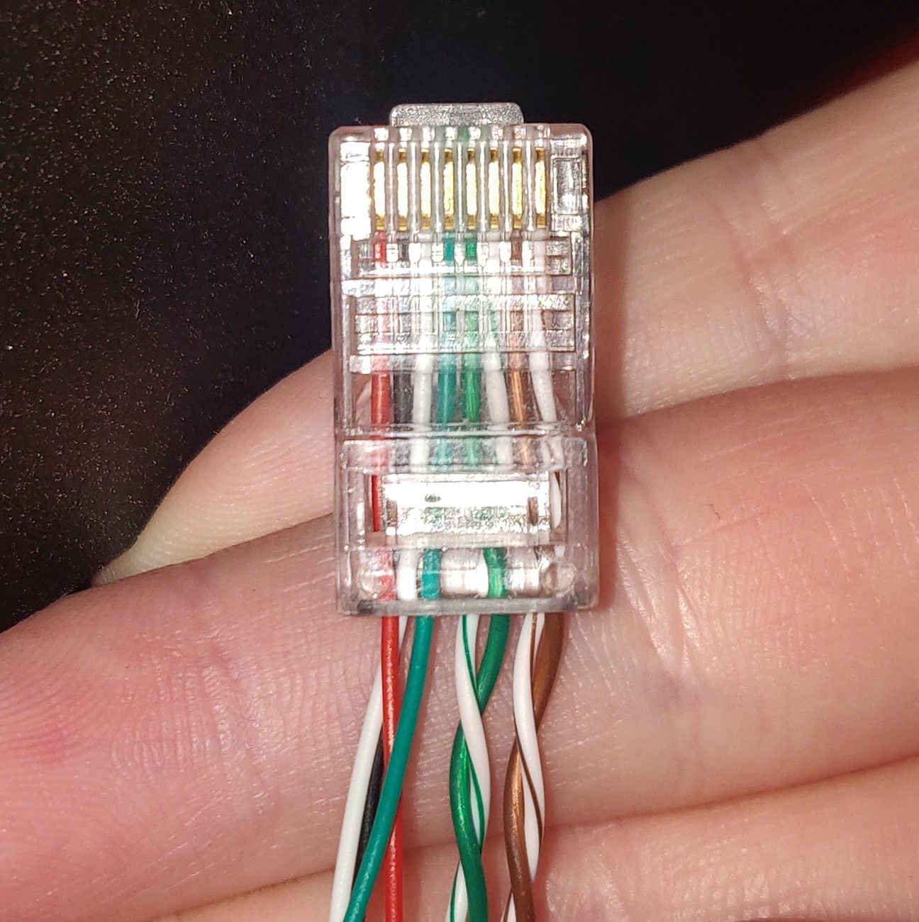
Make sure that all wires are fully inserted in the connector before you crimp it, but also ensure that no part of the wires extend through the connector if your connector does not stop wires from going through the entire assembly.
Connect the crimped RJ45 connector to the keystone that is connected to the HX711 board.
Cable management
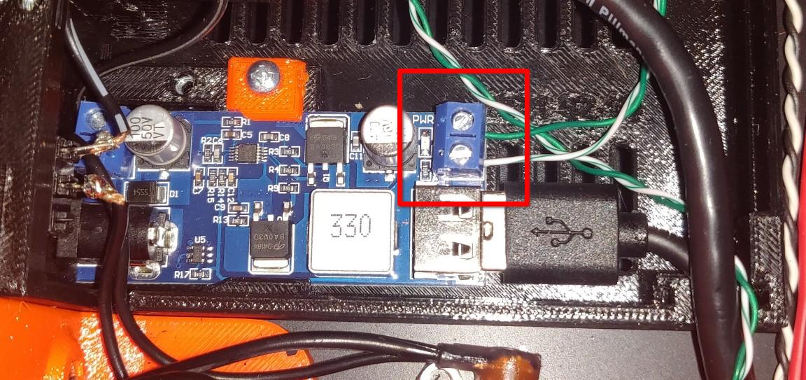
Route the two twisted wire pairs down behind the vertical cable management cover in the back corner of your printer enclosure. The green wire pair should be directed into the enclosure's power supply box and connected to the 5V screw terminals of the 12V-5V buck converter (the one that the USB cable from your Pi is connected to). Cut off the excess wire from this green wire pair and strip off about 5 mm of insulation from the ends. Twist the copper strands, the insert the wires as follows:
- Green to +5V
- Green/white to ground
Route the brown twisted wire pair behind the cable management covers and over to your Raspberry Pi. Ensure that the twisted pair wires can reach all the way to the GPIO headers of the Pi. Cut off any excess wire if you like.
Use the two Scotchlok connectors and insert the following wires into them:
- First connector: Brown twisted pair wire, and other half of the brown Dupont terminated wire from before
- Second connector: Brown/white twisted pair wire, and other half of the blue Dupont terminated wire from before
When two wires are inserted into one of the Scotchlok connectors, you can terminate it using pliers.
Raspberry Pi setup
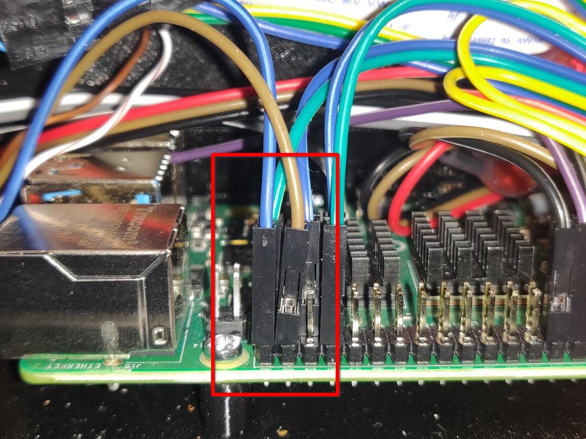
Connect the brown wire to GPIO pin 20, and the blue wire to GPIO pin 21, as indicated below:
Connect power and boot up your Raspberry Pi. In OctoPrint, install Filament Scale Enhanced. After installation, reboot OctoPrint and enter plugin settings.
Remove any filament spool from the filament holder, but leave the holder itself; remove only the spool! Press Tare to calibrate the weight of an empty spool holder. Measure the weight of the spool with filament on it using a kitchen scale, and place the spool back on the filament holder. Write the reading from the kitchen scale in the "known weight" box to calibrate the OctoPrint scale, then press Calibrate.
Finally, enter the weight of an empty spool. For Prusament spools, this is 193 grams. Yours may vary depending on which manufacturer of filament you usually use.